
Head lift is only affected by the elevation difference but not the shape of the Pipeline.
Head lift determines how high fluids can be pushed up: only the vertical distance, or the difference between the elevation of starting and ending points matter; it does not depends the Pipeline's shape. Each meter of head lift can lift the fluid by 1 meter vertically. Fluids can flow freely along perfect horizontal Pipelines.
Head lift does not depends on the flow rate, but can affect it.
The following buildings can generate head lift:
 Pipeline Pump - 20 meters
- Water Extractor, Oil Extractor, Refinery, Fluid Freight Platform - 10 meters
The following buildings can store and relay head lift:
- Industrial Fluid Buffer - up to 12 meters
- Fluid Buffer - up to 8 meters
- Pipeline - horizontal: 1.3 meters, vertical: same as pipe length
For example, Water Extractor output Water with a head lift of 10 meters, this means the Water Extractor can push Water up to 10 meters vertically.
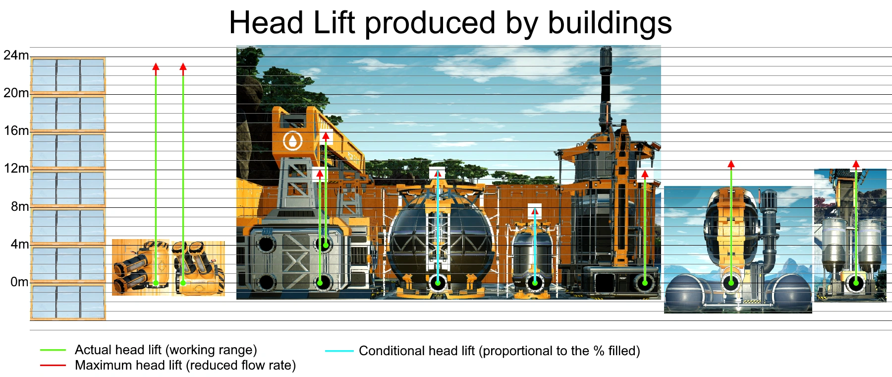
Head lift produced by different buildings have different base starting point, see below.
Head lift and elevation difference
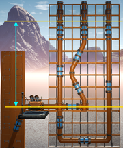
The head lift required to fill a fluid containment is equal to the elevation difference, measured from the base point of the source of head lift to the top level of the fluid containment.
Diagonal Pipeline is an exception: the reading of head lift, as displayed on a Pipeline Pump, will be slightly higher and not linear.
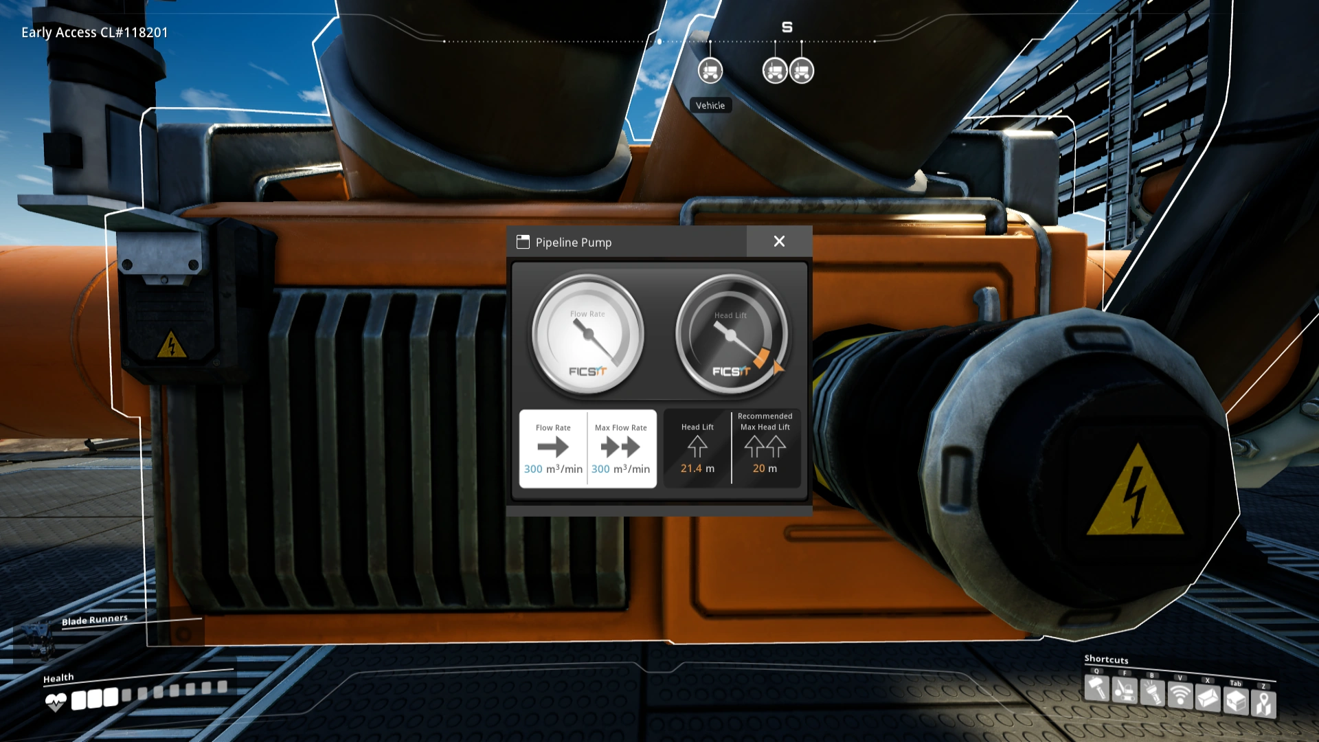
Currently the only way to measure head lift is by constructing a Pipeline Pump on the Pipeline at the elevation of measurement then interact E with it. You can estimate head lift by calculating the elevation difference, using walls (4 meters high) or foundations (4m, 2m or 1m)
Recommended, actual and maximum head lift
The recommended head lift can be found in the building's description in the build menu. Within the recommended head lift, fluids flow freely without resistance. The system may continue to work 1 or 2 meters higher than that, which marks the actual head lift. Beyond that, flow rate drops abruptly, down to zero flow around 2 to 3 meters beyond the recommended head lift, which marks the 'maximum head lift'. When approaching the maximum head lift, fluids start to act in strange ways: fluid may or may not flow, and may sometimes oscillate forward and backward while attempting to achieve the head lift equilibrium, producing inconsistent behavior. Thus, it is always recommended to keep the system within the actual head lift.
| Building | Head lift (meter) | ||
|---|---|---|---|
| Recommended | Actual | Maximum | |
| Pipeline Pump | 20 | 22 | 23 |
| Water Extractor | 10 | 12 | 13 |
| Oil Extractor | 10 | 12 | 13 |
| Refinery | 10 | 11 | 13 |
| Fluid Buffer* | 8 | 8 | 8 |
| Industrial Fluid Buffer* | 12 | 12 | 12 |
| Fluid Freight Platform (bottom outlet) | 10 | 11 | 13 |
| Fluid Freight Platform (top outlet) | 10 | 11 | 13 |
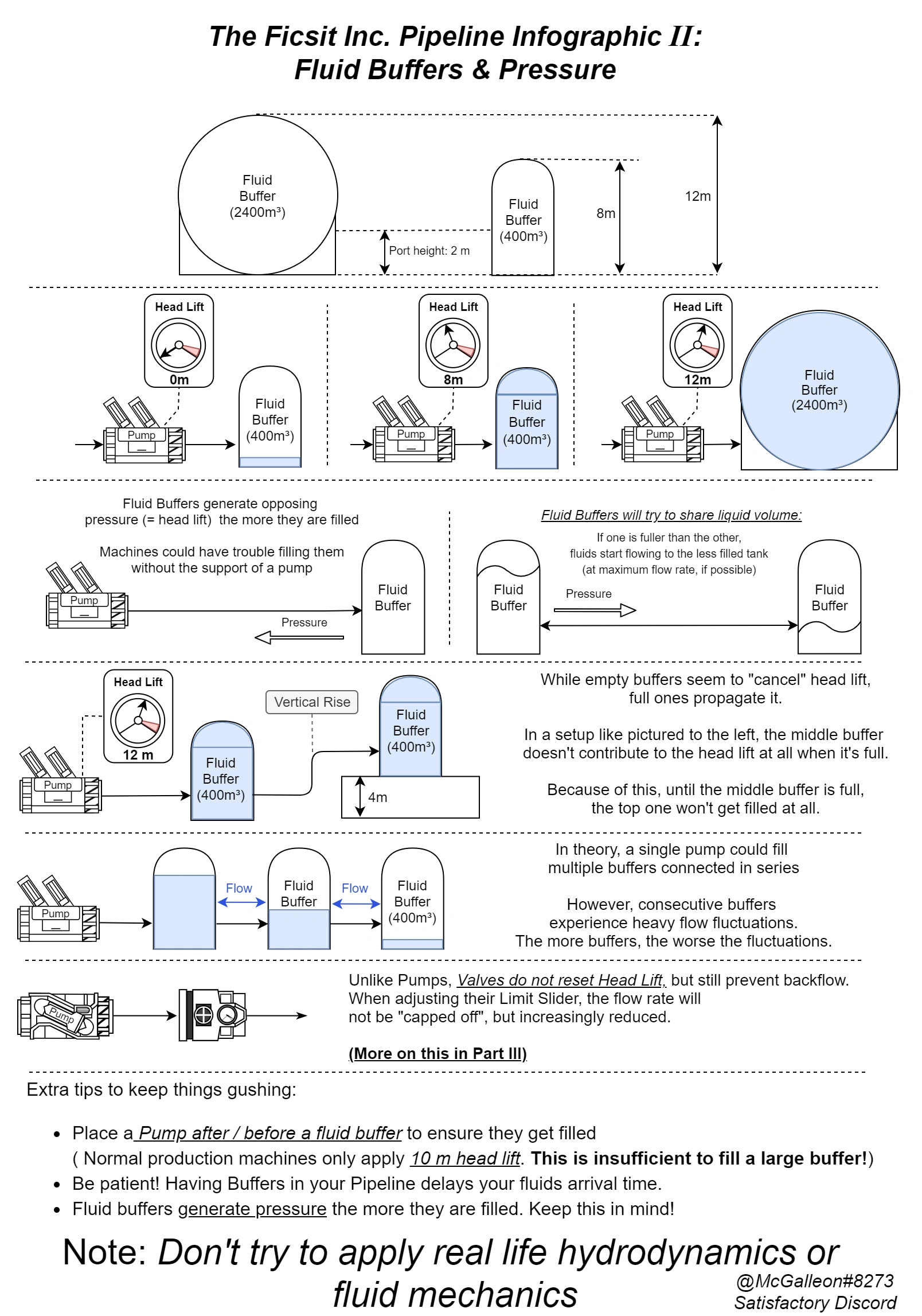
Note: Fluid Buffer and Industrial Fluid Buffer produce head lift proportional to the percentage filled. For instance, a half-filled buffer will produce half of the head lift.
Pipelines and Fluid Buffers
Perfect horizontal Pipelines require 1.3 meters of head lift to be fully filled regardless of its length. As it fills up, it also stores its own head lift proportionally, up to 1.3 meters. This effect will then propagate to the next pipeline and causes the successive pipelines to be filled up. Only when a segment of pipeline is fully filled, the head lift of more than 1.3 meters can be propagated (be it from a pump or other buildings). Fluids take time to fill up a very long pipe, but once it is fully filled, fluids in it can flow with the full flow rate (or whatever the source's flow rate).
Vertical pipelines can store maximum head lift equal to its vertical length, measured from its bottom end to the top end. Its stored head lift is proportional to the percentage of the fluid filled, for instance a half-filled 10-meters pipeline stores 5 meters of head lift. A vertical pipeline needs to be fully filled before the next pipeline above it can start to receive fluid. A very tall pipe requires a very high head lift to be fully filled. If lower head lift is provided, it can only be filled partially.
If somehow the fluid source is stopped and the source head lift drops, the previously stored head lift in pipes will attempt to equalize among connected pipelines: this means fluids can backflow from the pipes with higher head lift to the pipes with lower head lift, as pipelines are bi-directional in nature. Lets say, if there are 2 horizontal pipelines with identical length are connected in series, with 1 of them fully filled and the other one emptied, then the fluid within them will equalize themselves until both are filled equally, that is, 50% full. During this equalization process, the fluid flow can oscillate back and forth, taking a long time before fully stabilize.
All of the above principles also hold true for Fluid Buffers and Industrial Fluid Buffers - they are just pipelines but with much larger capacity and head lift. Just take note their stored head lift is counted from the pipe inlet level, not from the foundation level. Combining all the above knowledge, chaining multiple Fluid Buffers in series is a bad idea as the system requires a very long start up time - consider attaching buffers to the 'sideways' of a pipeline instead, by using Junctions.

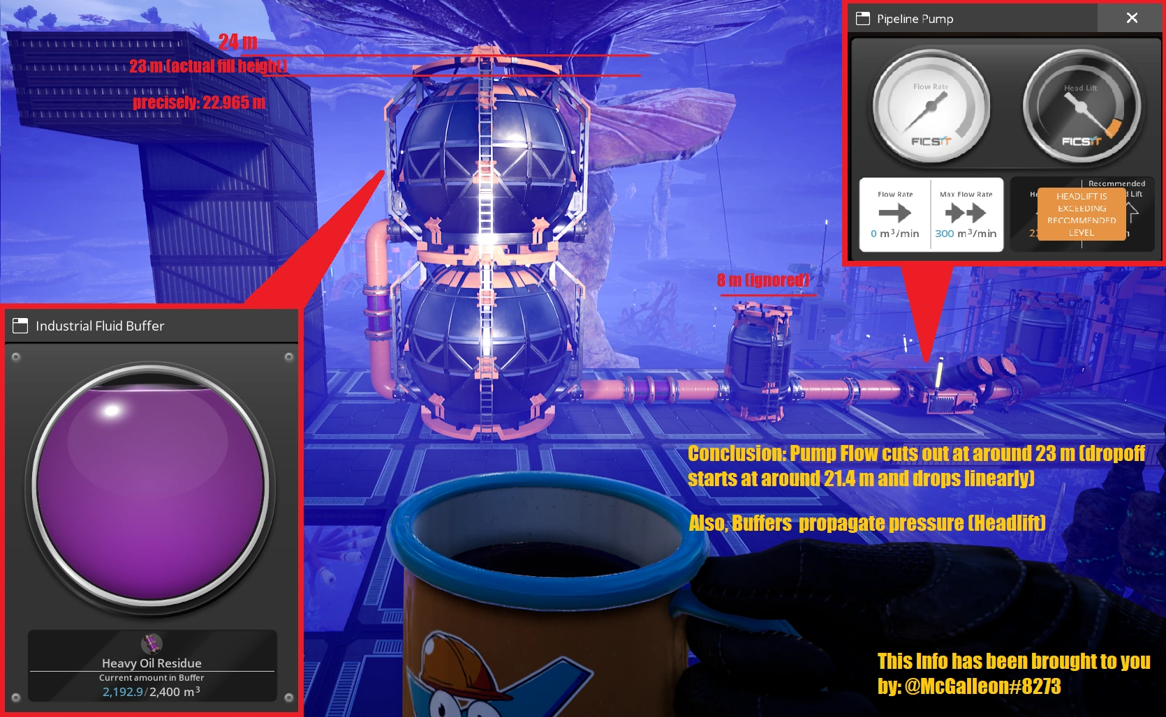
Buffers propagate headlift proportional to their fill height

A short guide detaling Buffer Head Lift and behaviour in combination with Pipeline Pumps

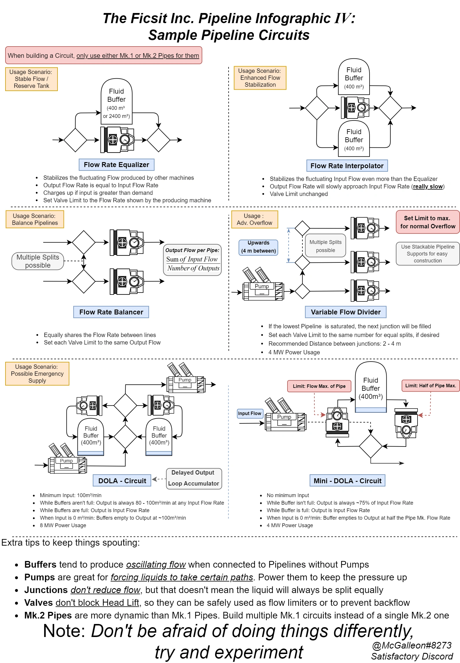
A collection of sample Pipeline builds, including Overflow, Input Manifold and Line Balancer.
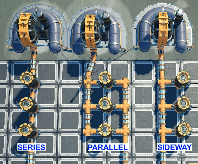
Different styles of connecting Fluid Buffers into Pipeline.
Head lift merging and splitting
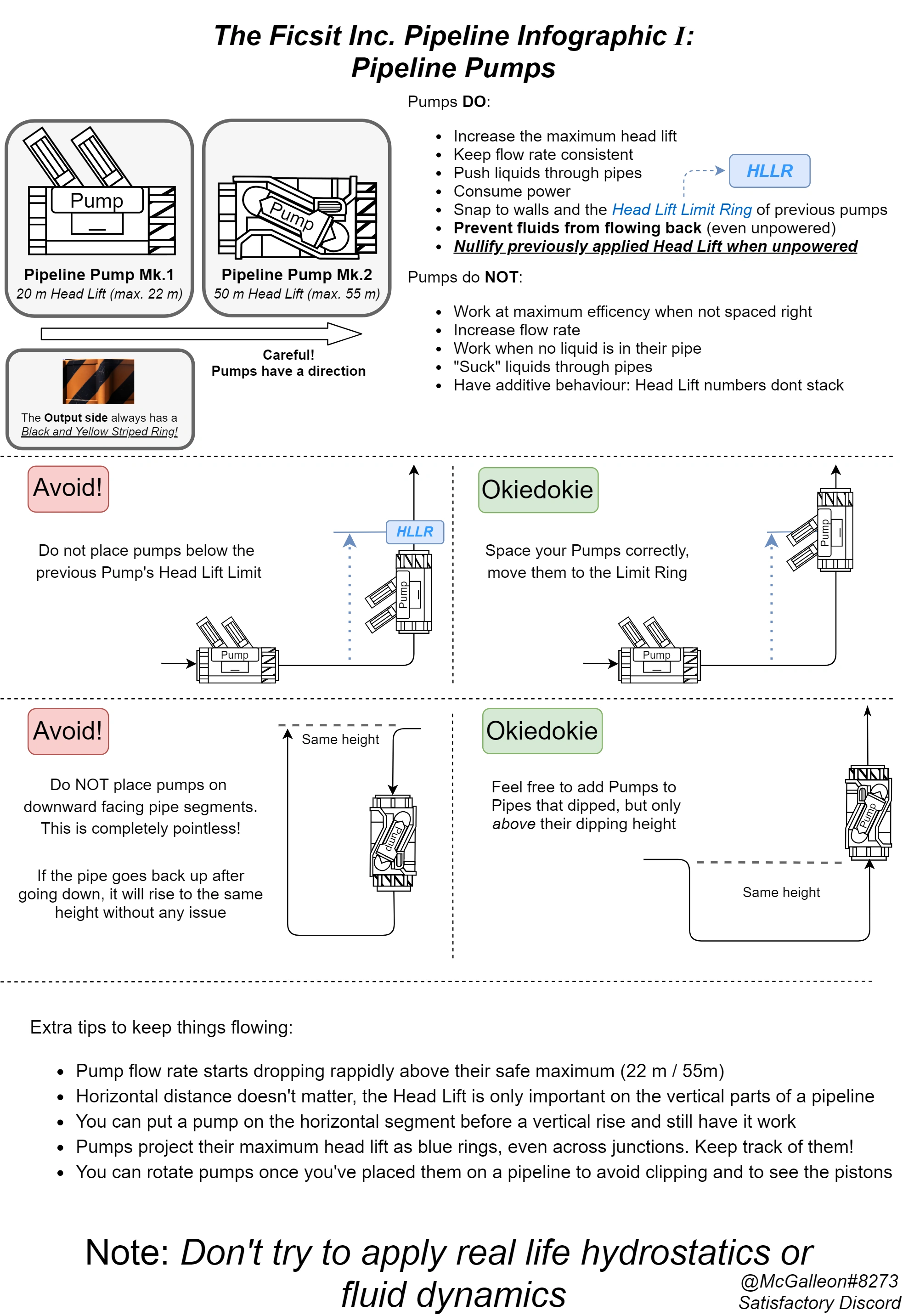
Pipeline Pump behavior and usage
When a single fluid source is split into multiple Pipelines via a Pipeline Junction Cross, the output head lift of each pipe is equal to the input. outA = outB = in The flow rate is split, but the head lift is not.
When multiple fluid sources with different head lifts are joint via a Pipeline Junction Cross, the highest head lift among them is applied to the entire pipe network. out = Max (inA, inB) This 'sharing' effect will not hinder the output of fluid buildings with lower head lift or positioned at the lower points, for instance, a Water Extractor with its output pipe under a head lift of much greater than 12 meters will still be able to push out Water, provided there is space allowed for it to.
Both of the above hold true regardless of the flow rate of input and output Pipelines.
Pipeline Pumps
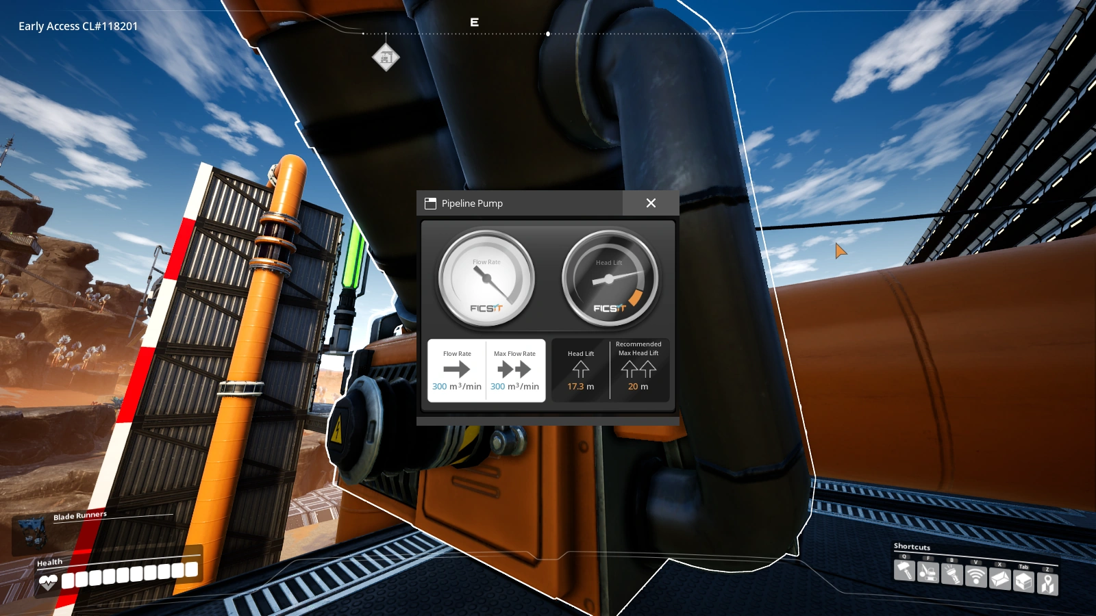
A non-powered Pipeline Pump acts as a one-way valve and resets the head lift back to 0 meter. A powered Pipeline Pump resets the head lift to 22 meters as long as there is fluid reaching its input, regardless of the head lift preceding it. That also means building multiple Pipeline Pumps in close proximity is very inefficient, and each of them costs power to function. Pipeline Pumps should be spaced out 22 meters vertically, measured center-to-center.
Pipeline Pumps continue to function with full flow rate even at 2 meters above its recommended head lift.
Exploits
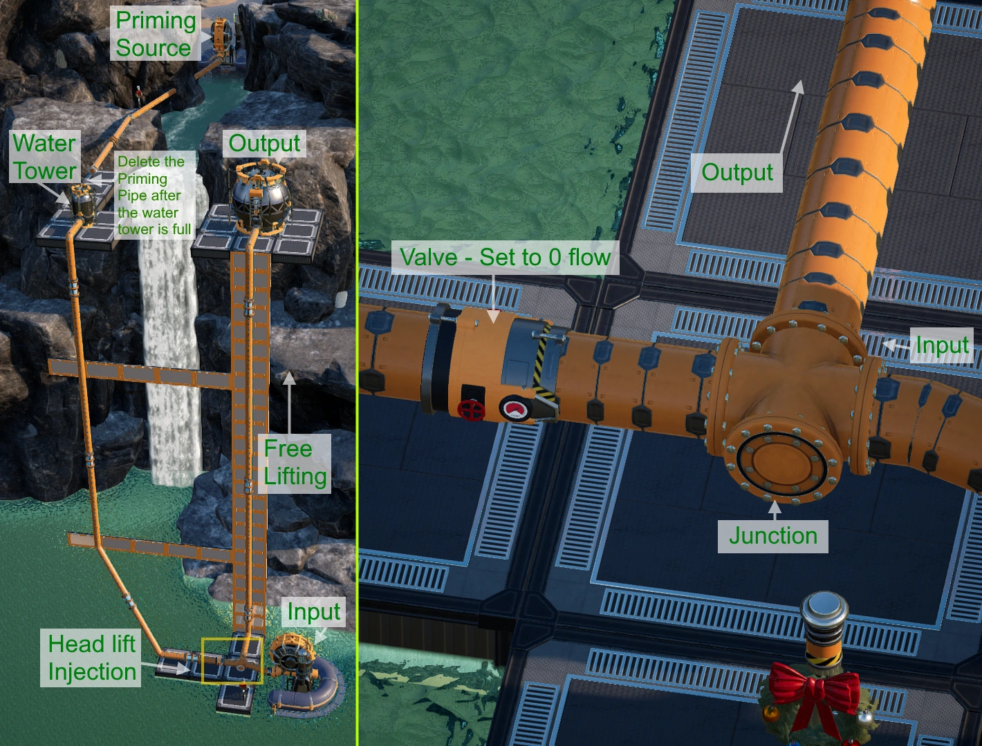
Pipeline pumps, if used in large quantity, can be a burden to the Power grid, thus innovative solution is highly desirable to minimize the power usage. When multiple fluid sources with different head lifts are connected to a single or multiple pipelines, the highest head lift among them will be applied to the entire connected pipe network. This makes head lift exploits possible, provided water bodies at different heights are in close proximity such as near the waterfalls.[1]
- To do so, first construct as many Water Extractors at the lower water body as you need.
- Build a floating factory above the lower extractors, but not more than 10 meters higher than the upper water level. Connect the pipes between the factory needing the Water and those extractors.
- Construct 1 Water Extractor at the upper water body. Extend a water pipe down the waterfall and to connect this extractor to all the other pipes at the lower part.
- All the pipes will then share the head lift of the highest water extractor.
- For this setup, Pipeline Pump is not required at all.
- If a waterfall is not available, a priming pipe can be built by applying an upward pipe boosted by pipeline pumps until a high point, then return downward and connect to multiple lower pipes to share its head lift among them.
The infograph showing head lift exploits.
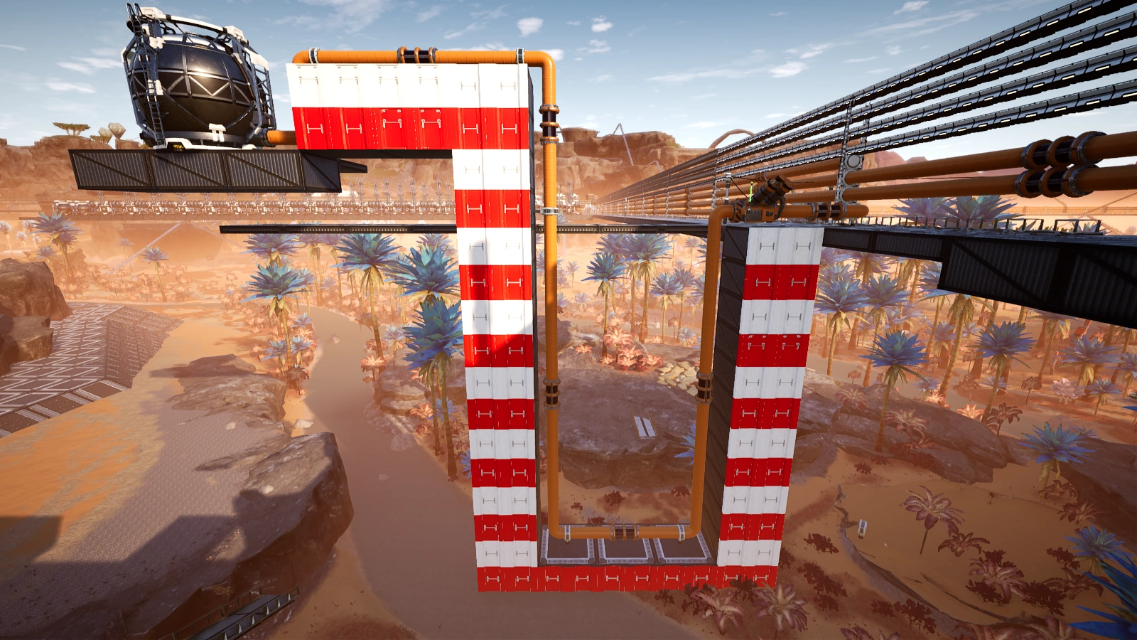
The waterfall exploit in game. Although the priming pipe is only supplied by a single Water Extractor (120/min), all 5 buffers are being filled at 300/min. Pump is not required.

The same technique can be applied to Oil-related fluids, just replace Water Extractors with Oil Extractors or Refineries.
Fluid Freight Platform
A Fluid Freight Platform does not generate opposing head lift when being filled up, and thus a fluid source can easily fully fill it up as long as the pipe inlet level of the Fluid Platform is within the source's head lift. As such it is advised to always use its lower pipe inlet first, followed by the upper inlet if the input rate higher than 300 m3/min is desired.
A Fluid Freight Platform requires a connected powered Train Station to receive and / or output fluid. It can output fluid regardless if it is set to load or unload.
The actual head lift provided by a Fluid Freight Platform is 11 meters, measured from the pipe connector. As such, it is always advantageous to use the upper pipe outlet first, followed by the lower outlet if the output rate higher than 300 m3/min is desired.
Gallery
| |||||||||||||||||||||||||||||